Android 12 Electronics mounting and initial testing
Android 12 Electronics assembly.
This page is about Android 12’s electronics assembly and initial testing, check out the project index for the rest.
As with the rest of the android, all of the parts will be 3D printed, so my initial work is to design the pieces in CAD. I’m usingAutodesk 123D, which is free software. Most of the electronics are taken from Android 11. There’s some YouTube videos explaining the operation so far.


I have to mount batteries and electronics on the Android, so I’ll need some more 3D printed parts. The first parts are the battery holders. I’m using a pair of old Ni-Cad batteries which I already had – this will be fine for initial testing but I may upgrade them in the future:


The microcontroller and servo controllers need a place to live. There will be three enclosures all together, the first the sits centrally between the batteries and mounts onto the spine. This has a shelf which the microcontroller can sit onto, and pilot holes to mount another. There are also a pair of side panels which will hold the servo controllers:


Here are the actual pieces, all that remains is to install the electronics:


The electronics are taken from Android 11, and currently consist of two Pololu Mini-Maestro controllers, and a Picxe-18 board with an IR receiver kit:

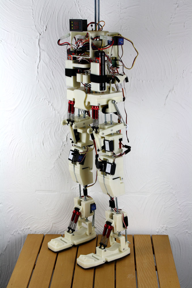
Here are some pictures of most of the electronics mounted. Each leg gets its own servo controller, and I’ve also added a voltage/current meter to monitor the batteries. The original Ni-Cad batteries were dead so I’ve replaced with a pair of Ni-Mhi batteries. They are wired in series to feed a 12-24v input 5v/10A output regulator which will power the servos.


Related Posts


About The Author
James Bruton
My name is James Bruton, I live in Southampton, UK. Please note that this is my personal project website, I have no products for sale, most of the information is provided so that you can have a go yourself... Read More