How to wire an LED
This page is about wiring LEDs, check out the main index for the rest.
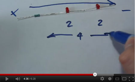
There is a YouTube video about this, or scroll down for the written version with pictures.
A typical LED is pictured below:
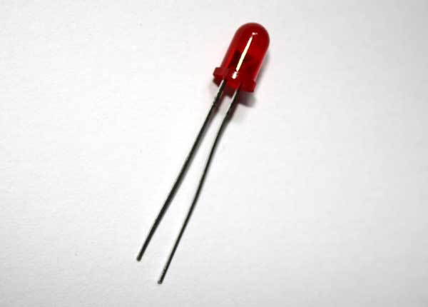
This is a 5mm diameter LED. LED stands for Light Emitting Diode. A diode only allow current to pass in one direction so the LED must be wired the correct way around.
One leg is shorter than the other, and on this side of the red plastic part there is a ‘flat’ part in the round casing. This pin is the cathode which goes to the lowest potential difference of it’s power source (the negative pin). The other pin is the anode which goes to the highest potential difference of it’s power source (the positive).
The specific rating of this particular LED is 2 volts at 20mA (0.02 Amps). This means that with a potential difference of two volts between the anode and the cathode, the current flow will be 20mA. The LED will only draw the current it requires, provided the potential difference remains correct. We could increase the current flow by increasing the potential difference but this would result in the LED getting unhappy with us and eventually failing. This is like increasing the pressure flow of water in our hose pipe – eventually the pressure would be too much and the pipe would burst.
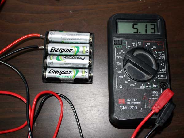
I’m going to use a battery pack to power this LED. The pack is made from four AA batteries – typically these are 1.5 volts each and they are wired in ‘series’ which means they are wired end-to-end like a string of sausages. For that reason the total potential difference cross the battery pack is 6 volts. However my batteries are rechargeable, and in the majority of cases rechargeable batteries are only 1.2 volts each, so my pack is around 4.8 volts in total. Measuring it with no load on (it will drop if there is a heavy current draw), shows a potential difference of around 5 volts, so that is the number we will work with:
In order to restrict the current flow through the LED, we will need to add a resistance into the circuit. This is like squeezing the hose pipe. We have a total of 5 volts across the battery, but the LED is only rated at 2 volts, so we need to drop the extra 3 volts across the resistor. We need 20mA (0.02Amps) to flow through the circuit so we will use Ohms Law:
R = V/I
R = 3/0.02
R = 150
So we need a resistor which is 150 Ohms.
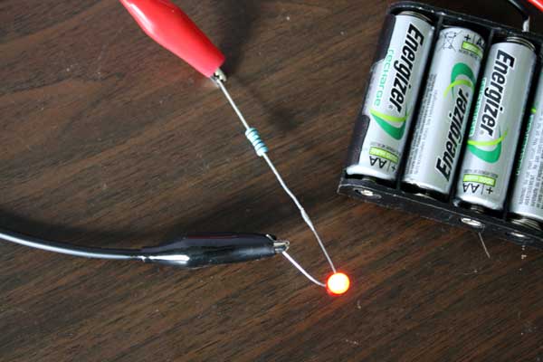
I’ve wired a 150 Ohm resistor to the anode of the LED, although you could wire it to either pin. The resistor can go either way around:
Related Posts


About The Author
James Bruton
My name is James Bruton, I live in Southampton, UK. Please note that this is my personal project website, I have no products for sale, most of the information is provided so that you can have a go yourself... Read More